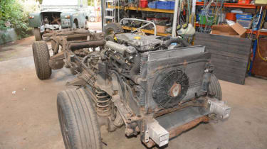
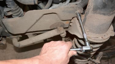
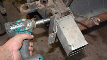
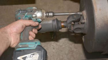
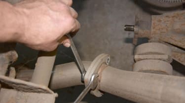
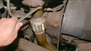
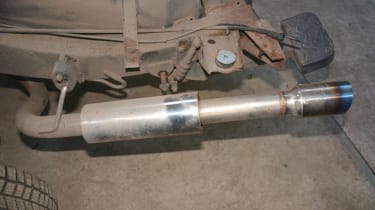
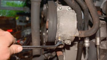
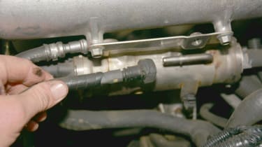
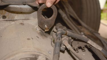
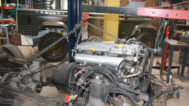
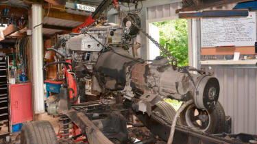
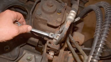
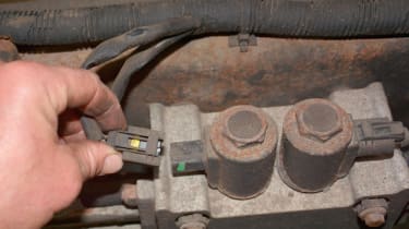
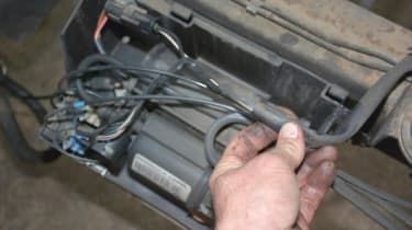
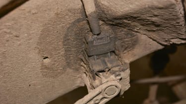
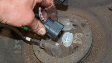
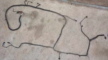
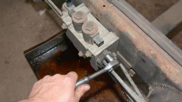
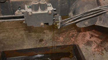
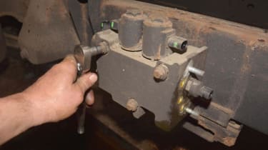
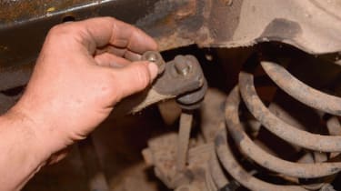
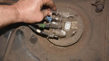
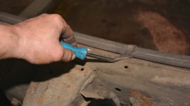
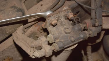
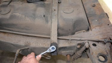
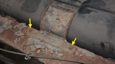
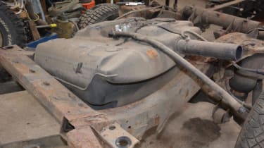
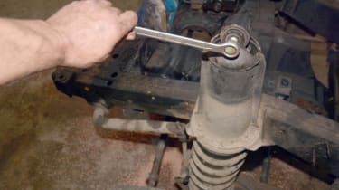
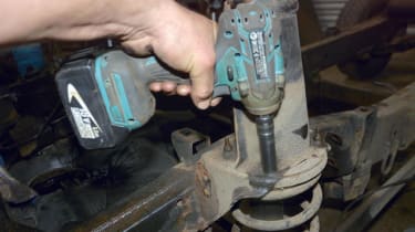
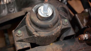
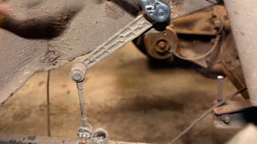
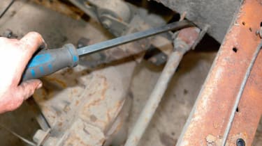
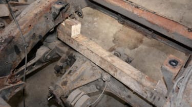
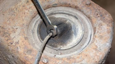
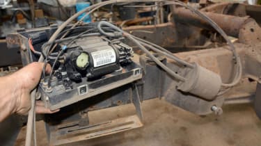
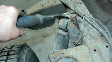
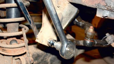
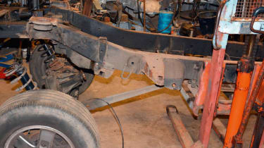
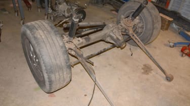
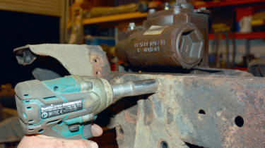
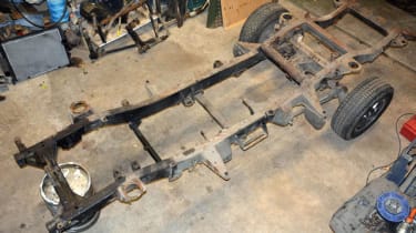
<span>Removing the engine: The D2 rolling chassis is a fairly conventional layout, but with additional. First job is to remove the radiator, intercooler and aircon evap to avoid damaging them.</span>
<span>These plastic side covers at both sides of the engine are removed to allow access to the hoses, cables and pipes protected behind them.</span>
- Skip advertAdvertisement - Gallery continues below
<span>The aluminium crush cans are unbolted from the chassis rails (13 mm spanner, 15 mm socket wrench, with impact gun for speed).</span>
<span>Prop shafts are disconnected from the transfer box and axles using a special 9/16th socket, made for Land Rover drivetrains.</span>
- Skip advertAdvertisement - Gallery continues below
<span>The exhaust system is broken down into sections by removing the bolts at each joint, here 13 mm spanners remove the M8 bolts.</span>
<span>The exhaust downpipe is disconnected from the exhaust manifold. This is a recently fitted stainless steel system, so it is easy to remove.</span>
- Skip advertAdvertisement - Gallery continues below
<span>The stainless steel tailpipe section shows a stark contrast of good fresh steel against sections of the chassis, on which rust has really taken hold.</span>
<span>At the engine, the hose feeding the ACE system is disconnected from the ACE pump, using a 15 mm spanner. The fluid is caught in a large drip tray.</span>
- Skip advertAdvertisement - Gallery continues below
<span>The fuel pipes on the fuel cooler at the engine are disconnected by squeezing the sides of the bayonet fitting, while pulling the pipe away.</span>
<span>Most transfer gearboxes have this stud present, which makes an ideal lifting point. Here a modified lifting eye is fitted over it and secured with an M10 nut.</span>
- Skip advertAdvertisement - Gallery continues below
<span>With chains at three lifting points (two on engine), the crane takes the strain. Nuts on the engine and gearbox mounts are removed, and the unit lifted.</span>
<span>The raised engine/gearbox is not sufficiently stable to be moved with the crane. Instead, the chassis is rolled out from underneath.</span>
- Skip advertAdvertisement - Gallery continues below
<span>The lump is then lowered almost to the floor, to a much more stable height. I find using pliers on the control valve offers much more control.</span>
<span>Wiring loom and ace: Now that the engine is safely out of the way, the other systems can be stripped. Here power steering pipes are disconnected from the steering box.</span>
- Skip advertAdvertisement - Gallery continues below
<span>The main wiring loom is attached along the top of the chassis rail. Careful prying with this trim tool means that the clips can be reused.</span>
<span>At the ACE system valve block on the chassis, the loom is disconnected by pressing the clips and pulling the plugs firmly away.</span>
- Skip advertAdvertisement - Gallery continues below
<span>Similarly, at the other side of the chassis, the loom connections to the air suspension compressor are removed, taking note of which wire goes where.</span>
<span>The wiring loom connections to the ride height sensors need careful handling when being disconnected as they are usually well bound with dirt.</span>
- Skip advertAdvertisement - Gallery continues below
<span>The connection to the fuel tank, that powers the fuel pump and fuel gauge, is unplugged by pressing the side clips in and easing the plug off.</span>
<span>Here the loom is roughly laid out as on the chassis. Other plugs disconnected include the rear ABS and the fuel filter water sensor cable.</span>
- Skip advertAdvertisement - Gallery continues below
<span>With the loom out of the way, the ACE system is dealt with. Here the M8 nuts are removed from the pipe clamps, using a 13 mm socket wrench.</span>
<span>As the pipes are pulled from the valve block, expect lots of fluid to escape and have a suitable container ready to catch as much of it as possible.</span>
- Skip advertAdvertisement - Gallery continues below
<span>The valve block itself is held to the chassis rail by three long M8 bolts, into captive nuts in the chassis. A 13 mm socket wrench easily removes them.</span>
<span>The anti-roll bar sections of the ACE system, front and rear, are attached to the axles by link rods. The nuts can be rusted and often have to be cut away.</span>
- Skip advertAdvertisement - Gallery continues below
<span>Fuel system: Four fuel hoses are attached to the fuel tank. These are colour-coded according to their position. Take note or photograph of their colour-coded order for correct refitting.</span>
<span>The fuel hoses are disconnected from the fuel tank (fuel pump assembly) by pressing the sides of the clips and pulling them free.</span>
- Skip advertAdvertisement - Gallery continues below
<span>The fuel lines are attached along the chassis rail by a series of clips. If these are carefully prised off, they can be reused when refitting the fuel lines.</span>
<span>The fuel filter assembly is attached to a bracket on the chassis by M10 bolts. Unlike the Defender, there is no cover fitted to the fuel filter on the</span>
- Skip advertAdvertisement - Gallery continues below
<span>The tank is held down by a metal band across the top of the tank. This is held on each side by M8 bolts, removed using a 10 mm socket.</span>
<span>There is also a little bracket holding the tank at the front. The two bolts are removed from the captive nuts in the cross member with a 10 mm socket.</span>
- Skip advertAdvertisement - Gallery continues below
<span>Having earlier removed the heat shield from under the fuel tank, the tank can be lifted off the chassis, rather than dropping it down.</span>
<span>Axles and suspension: The front dampers are fixed at the top to the suspension turret by an M12 bolt. These are removed using an 18 mm spanner or socket wrench.</span>
- Skip advertAdvertisement - Gallery continues below
<span>The suspension turrets are held to the chassis by four M8 nuts on the studs of the isolator ring. A 13 mm socket on the impact wrench soon sorts them.</span>
<span>The engine mounting rubbers are fixed to the chassis by two bolts, needing a 15 mm socket below and an 18 mm above to remove them.</span>
- Skip advertAdvertisement - Gallery continues below
<span>The ride height sensors require a 7 mm socket to detach them from the chassis bracket and removal of the M8 bolt through the radius arm.</span>
<span>The Watts linkage arms are levered free of their chassis brackets after removal of the fixing bolts – which needs 19 mm and 21 mm sockets or spanners.</span>
- Skip advertAdvertisement - Gallery continues below
<span>When the air suspension system is disconnected, the chassis will drop to the rear axle. I use this timber contraption to hold the chassis up.</span>
<span>The timber sits nicely on to the top of the rear axle and the chassis will sit down on the wooden block, as soon as the air is released from the system.</span>
- Skip advertAdvertisement - Gallery continues below
<span>A 10 mm spanner is used to carefully unscrew the air hose on top of each spring, releasing the high pressure air in a controlled fashion.</span>
<span style="font-size: 0.8125em;">Having detached the air lines from the air springs, the complete air suspension compressor and associated air lines can be removed as one assembly</span>
- Skip advertAdvertisement - Gallery continues below
<span>The rear dampers are detached from the chassis bracket by removing the bolt (18 mm socket wrench) and prising them free of the bracket.</span>
<span>The Panhard rod on the front axle is attached to this impressive chassis bracket. The bolt is removed with a 24 mm socket wrench and spanner.</span>
- Skip advertAdvertisement - Gallery continues below
<span>Using my trusty pallet stacker truck, the chassis is lifted up clear of the front axle, to allow it to be rolled out from underneath.</span>
<span>Two bolts holding the radius arms to the chassis have been knocked out after removal of the nut with a 24 mm wrench, and the axle was rolled forward.</span>
- Skip advertAdvertisement - Gallery continues below
<span>Finally, the power steering box is removed from the chassis by taking out the four bolts with a 19 mm socket on the impact gun.</span>
<span>The chassis is ready to be rolled out of the workshop, wheelbarrow-style on the loosely fitted rear axle.</span>
- Skip advertAdvertisement - Gallery continues below
Recommended

Jaguar Land Rover stops car exports to the US in wake of Trump Tariffs

Land Rover’s theft problems subside as stolen car numbers hit three-year low

The scariest cars we've ever driven

JLR is moving in the opposite direction to VW-Audi and Hyundai-Kia, and that’s not a good thing
Most Popular

Secrets of the new Audi Q2 e-tron uncovered: £35k EV SUV coming soon

SEAT’s future unclear as brand held in limbo

New baby Land Rover Defender Sport on the way and we’ve spotted it testing